Phone: +86-755-2357-1819 Mobile: +86-185-7640-5228 Email: sales@ominipcba.com whatsapp: +8618576405228

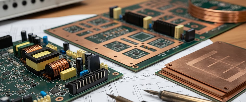
Heavy Copper PCB Engineering: The Foundation of High-Current Power Electronics
Overcome thermal and current density limitations in power electronics. Master the fabrication and assembly challenges of Heavy Copper PCBs (3oz to 20oz) for rugged applications.
PCB TECHNOLOGYPCB MANUFACTURINGPCB ASSEMBLY
OminiPCBA
1/3/20266 min read
Powering cars with electricity plus squeezing more output from solar inverters changed how we use circuit boards. Not just paths for tiny signals anymore, these boards now handle heat and big electrical flows. That change made thick copper layers - over three ounces per square foot - a must-have instead of rare option. Built to last, such heavy-duty designs became essential in tough electronic systems. Tougher jobs demand tougher wiring, hidden beneath flat surfaces.
From 4oz to 20oz, heavy copper boards play by different physical laws than regular circuitry. When conductors grow taller or wider, impedance behaves differently - etching and layer bonding shift too. Instead of standard designs, engineers juggle heat tolerance, electrical insulation strength, and structural durability. High voltage demands balance; one weak point risks total failure out in the real world.
The Etching Paradox Shape and Space
Fabricating heavy copper circuitry is a battle against the isotropic nature of chemical etching. In standard 1oz (35µm) production, the lateral erosion (undercut) of the copper trace is minimal relative to the trace width. However, as the copper thickness increases to 10oz (350µm), the time required for the etchant to cut through the metal increases exponentially. Since the etchant removes material sideways as effectively as it digs downwards, the resulting trace profile is not rectangular but trapezoidal.
This "etch factor" significantly reduces the effective top width of the conductor compared to the design file. For a 10oz trace, the difference between the foot and the crown of the trace can exceed 100µm. If the designer fails to account for this reduction, the cross-sectional area will be insufficient for the target current, leading to localized hotspots and eventual fusing. Advanced EMS manufacturing facilities address this by applying substantial compensation factors to the artwork - essentially designing the traces wider than required to allow the process to shrink them to the correct dimension.
Thicker copper means wider gaps between traces. Deep grooves form between bulky copper parts, holding onto etching chemicals. When rinse steps lack intensity, leftover acid may lead to tiny metal spikes or rust later on. Because of this, thick copper designs demand much broader separation - on a 10oz circuit board, space between features often hits 15 to 20 mils instead of the usual 4.
Lamination Dynamics Without Resin Starvation
Perhaps the most formidable challenge in heavy copper fabrication is the lamination cycle. When bonding multi-layer boards, the prepreg (resin-impregnated glass cloth) must flow to fill the voids between the copper traces. With 200µm or 400µm tall copper features, the volume of resin required to fill the gaps is massive.
Deep inside the layers, standard prepreg leaves tiny gaps when resin does not spread fully. Where resin misses, air stays trapped - air that breaks down faster under voltage than epoxy ever would. Such pockets spark hidden arcs, slowly turning pathways into carbon trails. Failure begins there, quietly, where no eye can see.
Fighting this issue means using prepregs packed with more resin - these flow better when heated. Lamination steps get tweaked too, holding heat longer while the resin stays runny enough to reach tight spaces. Inside those gaps, it moves freely, almost like water seeping through cracks. At Ominipcba, they’ve seen pressure adjustments during layering make or break Hi-Pot tests for heavy-duty solar inverters. Picking the right materials matters just as much as how thick the copper gets laid down.
Copper Heat Sink Thermal Management
Few notice it, yet how well copper moves heat matters just as much as its load limit. About 390 watts per meter-kelvin - heat zips through it fast. When thick copper layers go in, the board stops being just a base; instead, it pulls warmth across wide zones where air carries it off.
Heat shows up where a MOSFET or IGBT connects during surface-mounted power setups. Moving it out fast stops things from overheating. Thick layers of copper spread that warmth sideways through the circuit board toward spots tied to metal frames or outer cooling parts. Laying heat flat like paper across the board means no extra sink chunks stuck on each part. Fewer pieces appear on material checklists because of this shift. Shaking around matters less now too.
A twist often shows up when copper handles heat dissipation. Uneven layers - say, thick grounding below paired with thin traces above - pull at different rates under high temperatures. That difference bends the board mid-oven, curving sharply edge-to-edge. Balance matters most here. Layer alignment must mirror itself, especially when metal runs deep.
The Assembly Problem Heat Resistance
Heavy copper shifts how boards are made, moving past simple creation into full assembly where problems show up. Because it moves heat so well when running, the material fights against joining parts together. What keeps things cool while working grabs hold of any new warmth too fast. Those thick copper layers pull energy from tools before connections can form. Heat meant for bonding vanishes into the metal’s depth.
Most typical heating patterns meant for regular circuit boards fail when applied to thick copper layers. Even if the flux inside the solder melts early, the metal pad stays underheated - refusing to bond well. Only after holding heat longer does the full board catch up in warmth, setting conditions right just before peak temperatures hit.
Heat can harm parts that do not tolerate temperature well. Instead of uniform exposure, targeted methods deliver warmth only to certain areas. Components like electrolytic capacitors tend to wear out when heated too long during joining processes. Plastic connectors face similar risks under prolonged high temperatures. Some modern techniques rely on localized approaches such as induction or selective application. These prevent unnecessary heating across the whole board by focusing effort exactly where it belongs.
Carry Limits and Connection Reliability
Many think regular vias manage large currents just by linking to thick copper. Yet a usual plated hole gets about 20 to 25 micrometers thick at the walls. When fifty amps move from a 6oz layer through one normal via, it overheats like a weak link. That connection breaks under pressure.
When big currents switch layers, clusters of vias are often needed - or special methods that coat the hole walls thicker, sometimes beyond fifty microns. Another option uses solid copper inserts or flat conductors built right into the board for moving heavy current between levels. These connections face tough stress when temperatures change repeatedly. As heat shifts happen, the circuit board material stretches much more straight through its thickness than the copper does inside the holes. Heavy copper circuit boards push stress straight into the via barrel because the thick inner layers resist bending. To check if the plating can stretch without breaking, tests need sharp temperature swings.
Surface Smoothness and Flatness
Bumpy by design, heavy copper PCBs show clear bumps across their surface. Where copper rises, the gap from the flat base grows obvious. Uneven spots mess up how stencils press down during printing. When contact fails, paste leaks through openings it should not. That spillover links connections meant to stay apart.
Still, bumping up the solder mask helps fill dips - though only so much. When tiny parts sit near thick copper runs, what sits on top matters a lot. Hot Air Solder Leveling? Not ideal here - the blasts miss spots across wide areas, trapping blobs. Instead, flat finishes like dipped silver or nickel-gold work better. They keep everything steady under little chips, right next to bulky coils.
Mechanical Strength and Connection Reliability
Heavy wires usually connect through strong screw terminals in power electronics. Because of this setup, any force used on those screws travels straight into the circuit board. When fastening such terminals, ordinary boards risk having their copper pads ripped from the base material. It happens easily under pressure - no warning, just damage.
Peel strength improves dramatically with heavy copper. Because the trace bonds across more laminate surface, plus the metal holds its shape well, connections stay firmly locked. When demands get tough, Ominipcba shifts to slot-plated openings instead of circular ones for connector pins - this widens contact space while stopping pin spin when putting things together.
A Balanced Way to Handle Energy
Out of nowhere, heavy copper PCB work steps beyond basic materials into full-scale engineering craft. Working well together becomes essential - designer, builder, and assembler each play distinct roles. While the designer focuses on precision etching and heat distribution, the fabrication side tackles bubble-free layer bonding and deep plating tasks. On arrival at assembly, careful heating schedules take over, securing solid connections but skipping harm to parts.
Built right, these thick-copper circuits pack serious punch - cooling down high-stress systems while lasting longer under strain. Power flows smoother through them, helping future EVs push limits without overheating. Renewable setups lean on their toughness when feeding city-scale grids. Machines in tough factories run better, thanks to steady performance even at full tilt.
Related Articles
Contacts
Email: sales@ominipcba.com
Mobile: +86-185-7640-5228
Copyright © 2007-2026. Omini Electronics Limited. All rights reserved.
Head Office: +86-755-2357-1819
Services
Your China turnkey partner for electronics manufacturing. We bridge design to delivery by leveraging the Shenzhen electronics ecosystem for precision engineering and streamlined PCBA supply chain logistics.
Ready to Build?
Get a comprehensive quote within 24 hours.
